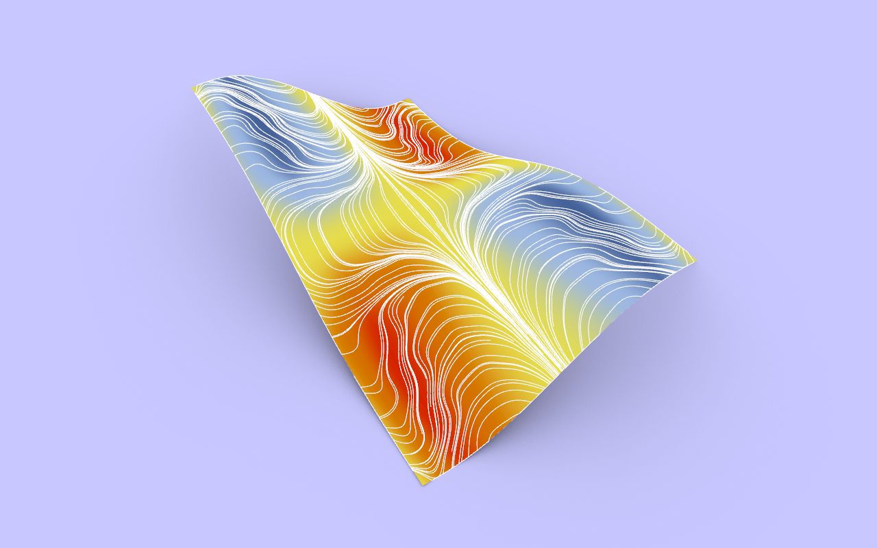
Surface Field Lines (Grasshopper Example)
This example uses the Fields Plus plugin developed at The Different Design. You can download the plugin here. This example looks closely at the Field Line Surface component, which allows field line simulations to occur directly on any input surface. These simulations can be used in conjunction with any field force or charges, and essentially snaps the lines directly to the input surface.
The Field Plus Plugin is available to download for all Premium members of The Different Design.
Not a member? Sign up today!
Download the Surface Field Lines example file.
The grasshopper example:
This example makes use of the Plane Force component together with the Field Line Surface component to simulate field lines on a surface in Rhino. The surface is divided up into a grid of frames. At the location of each frame, the surface curvature is measured, and then each frame is rotated around it’s Z-axis based on the surface curvature. This creates a collection of frames oriented based on the surface curvature at a specific point. Each of these rotated frames is input into a Plane Force component, which are merged to create a force field based on surface curvature.
This force field is then used to simulate a series of Field Lines on the surface from a collection of random starting points using the Populate Geometry component. The Field Lines generated from the definition create a flowline effect that responds to the curvature of the surface, so if the surface is updated, the lines update in accordance with the new curvature.
In the final definition, the example also includes a small addition that converts the surface to a coloured mesh geometry to clearly display the curvature as a coloured heat map.

The final algorithm showing the field lines flowing along the surface in response to curvature
Producing different iterations:
The Field Line Surface component can be used on any surface from Rhino to generate a collection of Field lines, and works by finding the closest point on the surface from any starting point. The component works best if starting points are generated on the surface from the beginning. In the examples below, the definition continues to use surface curvature to define the force field, but changes the rotation value, and plant force axis to simulate different outcomes and results.

A collection of iterations derived from the example by changing axis directions in the Plane Force component and maximum rotations of each plane.
Taking this a step further:
The component can be used with all field force and charge components to further affect the behaviour of the field lines. Try using it in combination with the Spin Force component, Point Charge component and Tangent Force component.
